Mi-24V Flight Manual part 1
Contents
- 1 PREPARING HELICOPTER TO FLIGHT
- 1.1 1.1 Preliminary Cockpit Inspection
- 1.2 1.2 Before Starting Engines
- 1.3 1.3 APU start
- 1.4 1.4 Engine start
- 1.4.1 1.4.1 Engine start, First Engine
- 1.4.2 1.4.2 During start up monitor that:
- 1.4.3 1.4.3 Compressor idle RPM check values:
- 1.4.4 1.4.4 Toggle engine selection switch and repeat actions 1.4.1-1.4.3 to start second engine.
- 1.4.5 1.4.5 After second engine reach idle RPM
- 1.4.6 1.4.6 Shut down APU (Ext Pwr only)
- 1.5 1.5 Before Taxi
- 1.5.1 1.5.1 Ensure, that main rotor revolutions is 95±2%
- 1.5.2 1.5.2 Switch supplying from ground power units on on-board generators
- 1.5.3 1.5.3 If DC ground supply or on-board batteries was used
- 1.5.4 1.5.4 Enable radio equipment:
- 1.5.5 1.5.5 Test radio equipment:
- 1.5.6 1.5.6 Check Doppler navigation system DISS-15
- 1.5.7 Appendix A: Fuel System
PREPARING HELICOPTER TO FLIGHT
1.1 Preliminary Cockpit Inspection
1.1.1 Check Battery Voltage
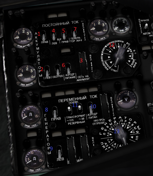
Turn on (1) [LEFT BATTERY][ЛЕВ.], (2) [Right BATTERY][ПРАВ.], (3)[BATTERIES SUPPLY][СЕТЬ НА АККУМУЛЯТ.], [N1 FUEL TANK PUMP][ЛЕВ. №1] and [N2 FUEL TANK PUMP][ПРАВ. №2] switches (voltage gauge should indicate at least 24 volts when DC test selector switch in (12)[Batteries][АККУМ.] position), turn off [BATTERIES SUPPLY][СЕТЬ НА АККУМУЛЯТ.], [N1 FUEL TANK PUMP][ЛЕВ. №1] and [N2 FUEL TANK PUMP][ПРАВ. №2] switches.
1.1.2 If External Power is available – AC Check
Command ground crew to connect External Power. [Press Enter and click the lightning symbol on Loadout Page] Turn on (10)[AC GROUNDFEED][АЭРОДР. ПИТАН.] switch, check that [GROUND FEED][РОЗЕТКА ВКЛ.] lamp is lights, ensure that voltage reads 200-208 volts when AC test selector switch in any position except (13)[Off][ОТКЛ] and “115”.
Set “115” and “36” transformers switches to (11)[MAIN][ОСНОВНОЙ] position, rectifiers switches to [ON][ВКЛ.] position and check that corresponding lamps above switches are off.
Red = DC Blue = AC
1.1.3 DC Check
Turn (6)[DC GROUNDFEED][АЭРОДР. ПИТАН.] and (3)[BATTERIES SUPPLY] to [ON][ВКЛ.] , [GROUND FEED][РОЗЕТКА] lamp should be lit. Turn on [PO-750A 115 CONVERTER][ПО-750А] switch and verify that [PO-750 OPRT][ВКЛ. ПО-750А] lamp is lit.
1.1.4. If no External Power available
Turn on batteries and check voltage.
Turn on [PO-750A 115 CONVERTER][ПО-750А] switch and check that [PO-750 OPRT][ВКЛ. ПО-750А] lamp is lit.
1.1.5 After power supply is established
- Check warning lamps operation: Press [Lamps test][КОНТРОЛЬ] button and ensure that all lamps are lit;
- Ensure that wheels brakes are functional (after engaging wheels brakes red warning lamp [PARK BRAKE][ТОРМОЗ КОЛЕС] is lit. Warning lamp should extinguish when wheel brakes disengaged);
- Close the door and command to Operator close canopy;
- Receive Operator's report that canopy closed: green [CKPT SEALED][ДВЕРИ ЗАГЕРМ.] lamp should illuminate.
- Check fuel quantity in the tanks and ensure that fuel indicator works properly;
- Ensure that engine and gears control gauges are working properly: Set the[DIM TRANSFORMER][ТРАНСФОРМ. ДИМ] switch to [AUX][РЕЗЕР.] position and ensure that gauges needles are moving and yellow lamp [DIM TRANSF][ОСН. ТРАНС. ДИМ ОТКЛЮЧ.] is lit. After checking set switch to the left [MAIN][ОСН.] position and the light should extinguish
1.2 Before Starting Engines
1.2.1 Disengage rotor brake
1.2.2 Check control handles and set them in proper position
- rudder to lower position;
- throttle grip to the left (Left Click on Cyclic Twist);
- cyclic handle move backward on 60mm and engage wheels brakes.
1.2.3 Ensure that generator switches are turned off
Warning lamps [L GEN INOPRT][ЛЕВ. ГЕН. ОТКЛ.] and [R GEN INOPRT][ПРАВ. ГЕН. ОТКЛ.] are illuminated
1.2.4 Prepare fuel system
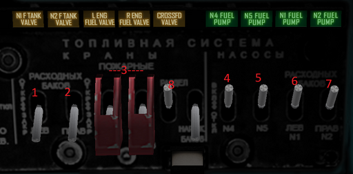
Open fuel feed tank valves (1,2), engine fire valves (3 – Right click in dashed area to unguard switches), fuel separator valve, turn on fuel pumps (4-7) [N1 FUEL TANK PUMP][ЛЕВ. №1], [N2 FUEL TANK PUMP][ПРАВ. №2], [N4 FUEL TANK PUMP][№4] and [N5 FUEL TANK PUMP][№5]; check that green status lamps above respective switches has lighted up and yellow warning lamps extinguished. Cross-feed as required for fuel load ( 8 – If any green light remains unlit. Light should come on within 10 seconds after crossfeed enable) and monitor Fuel distibution.
For fuel system in further detail Reference Appendix A.
1.3 APU start
1.3.1 Set APU mode switch to [ЗАПУСК]
Veryfy [APU GEN][ГЕНЕР. АИ-9В] is switched off.
Set DC voltage selector switch to position related current power supply type ( External or Battery), set [APU START MODE][РОД РАБОТ] switch to [START][ЗАПУСК] ( lower )position. Press [START APU][ЗАПУСК] button for 2-3 seconds, turn on stopwatch and wait until [AUTOMAT WORKING][АВТОМАТ ВКЛЮЧЕН] lights up. When APU reaches normal RPM, lamps [APU RPM][ОБОРОТЫ АИ-9В НОРМАЛЬН.], [AUTOMAT WORKING][АИ-9В РАБОТ.] and [APU OIL PSI][ДАВЛЕН. МАСЛА НОРМАЛЬН] will light up.
1.3.2 While start up monitor following values:
- exhaust gas temperature must not exceed 880°C;
- DC currents must be higher than 18 volts;
- normal oil pressure is indicated by [APU OIL PSI][ДАВЛЕН. МАСЛА НОРМАЛЬН] light. At the beginning of APU start blinking of this lamp can occur;
- time needed to reach idle RPM shouldn't exceed 20 seconds;
- Maximum time for starter engagement is 30 seconds, check that [AUTOMAT WORKING][АИ-9В РАБОТ.] lamp extinguishes after that amount of time.
-If any mentioned Values are exceeded, abort start and have the Aircraft inspected!
1.3.3 After APU reach normal RPM ensure that:
- green lamp [APU RPM][ОБОРОТЫ АИ-9В НОРМАЛЬН.] is illuminated;
- exhaust gas temperature is less than 720°C;
- lamp [APU OIL PSI][ДАВЛЕН. МАСЛА НОРМАЛЬН] is lit. This indicates normal oil Pressure of AI-9V engine.
1.3.4 Check APU generator before flight day
Turn on [APU GEN][ГЕНЕР. АИ-9В] switch. Output voltage should be 28-29 volts, exhaust temperature not more than 750*C.
After generator test is over turn off [APU GEN][ГЕНЕР. АИ-9В] switch (When External Power is connected).
1.3.5 APU air pressure
Can be monitored by manometer indication at left panel of Pilot's cockpit and should be within the values from graph 1.3 depending on external air temperature and density.
1.4 Engine start
1.4.1 Engine start, First Engine
Set [ENGINE START MODE][РОД РАБОТ] switch to [START][ЗАПУСК] position, [ENGINE SELECTOR][ЗАПУСК ДВИГАТ.] switch to [RIGHT][ПРАВЫЙ] or [LEFT][ЛЕВЫЙ]. Press [START ENGINE][ЗАПУСК] button for 1-2 seconds.
At 15% Compressor RPM move shutoff fuel valve to open (forward) position.
Compressor should reach idle (60%) RPM within 60 seconds.
1.4.2 During start up monitor that:
- automatic start panel operate properly, lamp [AUTOMAT WORKING][АВТОМАТ ВКЛЮЧЕН] is lit;
- air starter operation indicated by [ENGINE START][СТАРТЕР РАБОТАЕТ] lamp;
- compressor RPM increasing continuously (without freezing) and main rotor start to spin at around 25% compressor revolutions;
- EGT limits from graph. 1.4 shouldn't be exceeded.;
- sufficient oil pressure indicated by manometer on front panel, at 45% compressor revolutions pressure should be more than 1 kg/cm^2;
- starter cut out after compressor reaches idle RPM, [ENGINE START][СТАРТЕР РАБОТАЕТ] lamp goes out; if it fails to disengage, shut down starter manually by pressing [ENGINE STARTER SUSPEND][ПРЕКРАЩ. ЗАПУСКА] button; if [ENGINE START][СТАРТЕР РАБОТАЕТ] lamp still on, close shutoff valve of running engine and shut down APU by pressing [STOP APU][ОСТАНОВ АИ-9В] button and have the Aircraft inspected;
- Starter operation shouldn't exceed 33 seconds. If [AUTOMAT WORKING][АВТОМАТ ВКЛЮЧЕН] light is illuminated after that time period, abort starting process.
1.4.3 Compressor idle RPM check values:
- compressor RPM depends on external air temperature and should be in limits.
- EGT must not exceed 780*C;
- engine oil pressure must be 0.5kg/cm^2 or greater, oil temperature – more than -40°C.
WARNING: If less than 0.5kg/cm^2 is indicated, shut down engine immediately!
1.4.4 Toggle engine selection switch and repeat actions 1.4.1-1.4.3 to start second engine.
1.4.5 After second engine reach idle RPM
Check main rotor revolutions to be within 45-65%.
1.4.6 Shut down APU (Ext Pwr only)
Press [STOP APU][ОСТАНОВ АИ-9В] after it cooling for 0.5-1 minute.
If electrics system was supplied from batteries, do not shut down APU until engines are warmed up and throttle increased to 88% Rotor RPM. for powering necessary equipment turn on APU generator by moving [APU GEN][ГЕНЕР. АИ-9В] switch to [ON][ВКЛ] position.
1.5 Before Taxi
1.5.1 Ensure, that main rotor revolutions is 95±2%
If it's needed adjust throttle grip to reach required revolutions.
1.5.2 Switch supplying from ground power units on on-board generators
- turn on (8) [LEFT GEN][ЛЕВ] and (9) [RIGHT GEN][ПРАВ] AC generators switches, lamps [L GEN INOPRT][ЛЕВ. ГЕН. ОТКЛ.] and [R GEN INOPRT][ПРАВ. ГЕН. ОТКЛ.] should go out and [AC GEN OPRT][ПАРАЛЛЕЛ. РАБОТА ГЕНЕР.] will light up. Turn off (10) [AC GROUNDFEED][АЭРОДР. ПИТАН.] switch;
- command to ground crew to disconnect ground feed (Enter – Payload screen);
- check generators output voltage, that should be 203-204V for any AC test selector switch position except (13)[Off][ОТКЛ] and [115].
ATTENTION: after generators connected as power supplies, DO NOT decrease rotor revolutions below 86%, otherwise generators will trip.
1.5.3 If DC ground supply or on-board batteries was used
After generators are online, perform the following steps:
- activate ADF by turning on [ADF][КУРС. СИСТЕМА] switch and check it's operation. For this set [ADF MODE][МК — ГПК — ЗК] switch to [Magnetic slaving][МК] position Heading disc should indicate current azimuth;
- turn on both gyros by turning on [MAIN GYRO][ГИРОВЕРТИКАЛ. 1] and [AUX GYRO][ГИРОВЕРТИКАЛ. 2] switches, check gyros operation with artificial horizons PKP-72M and UKT-2. Warning lamps [GYRO 1 FAIL][ОТКАЗ ГИРОВЕР. 1] and [GYRO 2 FAIL][ОТКАЗ ГИРОВЕР. 2] should go out, red flags of PKP-72M and UKT-2 disappear, actual pitch and roll angles indicated properly;
1.5.4 Enable radio equipment:
- Turn on [HF RADIO][КВ], [VHF RADIO][УКВ], [ЭВКАЛ.-М24], [DISS][ДИСС], [RADIO ALTIMETER][РАДИОВЫСОТ.] and [SPO-15 POWER][СИРЕНА-3М ПИТАНИЕ] switches;
- Set ARK-15 MODE selector switch in required position (Compass).
- Turn on [ARK-U2 POWER][ВКЛ] switch on control panel of ARK-U2 radio compass.
1.5.5 Test radio equipment:
For radio stations test set [SPU-8 MODE][РАД.-СПУ] switch of SPU-8 panel to [External][РАД.], mode selector switch – to [VHF1][УК1] or [MW][СР] position. [R-860-1 MODE][АРК Р/СТ — Р/СТ] switch on R-860/R-863 radio panel set to [ADF + RADIO][АРК Р/СТ]l
- Radio altimeter RV-5 should indicate altitude value 15±1.5 when [RADIO ALTIMETER TEST][КОНТРОЛЬ] button is pressed. Adjust safe altitude value with [RADIO ALTIMETER SAFE ALT][УСТАН.ВЫСОТ.] on RV-5 gauge.
Inflight voice message “Lower the gears” appears if altitude drops below set limit and forward velocity less than 70km/h;
- check radio compass ARK-15 heading and direction finding with known beacons in less than 50km range. For that set mode switch on ARK-15 panel to position ([COMPASS][КОМ].
- set DISS mode selector on control panel to [Memory][ПАМЯТЬ] position;
- set [DISS SURFACE TYPE][С-М] and [DISS DRIFT TEST][К-Р] switches on drift indicator to [Land][С] and [Operate][Р];
- turn on [DISS][ДИСС] switch, lamp indicators [КОНТР.], [М] and [В] should light up, on drift indicator – [П] lamp;
- check system operation in calculation mode by moving DISS-15 mode selector switch to position Test 1, Test 2 and Test 3;
- check DISS-15 operation in “Sea” mode, moving [DISS SURFACE TYPE][С-М] switch to [Sea][М] position and mode selector switch to Test 1 position. Forward velocity value will be increased 3 km/h.
Left [DISS SURFACE TYPE][С-М] switch in [Land][С] or [Sea][М] position depending on surface in mission area;
- check position indicator operation - set to zero [DISS DISTANCE][ПУТЬ КМ], [DISS DRIFT][БОКОВОЕ УКЛОНЕНИЕ КМ], [УГОЛ КАРТЫ] counters with buttons [BCWD][Н], [FWD][В], [LFT][ВЛ], [RGHT][ВПР], “-” and “+”. While DISS-15 mode selector switch in Test 1 position press [DISS counters on][ВКЛ.] button on indicators panel (for 5 minutes counter [FWD][ВПЕРЕД] should show 11.3 km);
- check drift and forward velocity indicator – set [DISS DRIFT TEST][К-Р] in [TEST][К] position. Forward velocity indicator value should be (306±3.5) km/h, drift angle (15±1)*.
- check “Memory” mode – set mode selector switch to [Memory][ПАМЯТЬ] position. Forward velocity indicator should change not more than ±9 km/h, drift angle – less than ±3*. Lamp [П] on drift indicator will light up at same time. Set [DISS DRIFT TEST][К-Р] switch to [Operate][Р] position;
- check map-case operation for movement of caret when [MAP-CASE POWER][ВКЛ.-АВТ.-ОТКЛ.] switched in [ON][ВКЛ.] position and [DISS counters on][ВКЛ.] button on counters panel is pressed. After tests are finished set [MAP-CASE POWER][ВКЛ.-АВТ.-ОТКЛ.] to [OFF][ОТКЛ.].
Set DISS-15 mode selector switch to [OPERATE][РАБОТА] position.
Appendix A: Fuel System
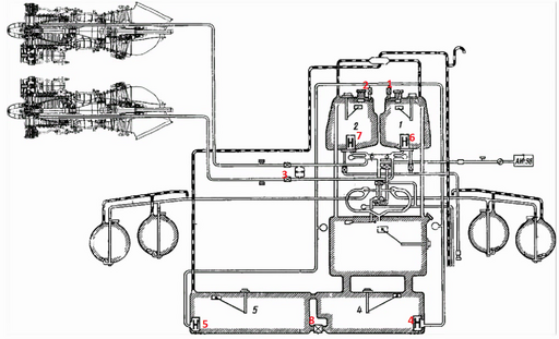
Fuel is distributed to the Engines from the corresponding engine Feed tanks (1,2). Should one pump fail Both engines will be fed from the remaining tank. If both pumps have failed fuel will be gravity fed to the engine, however any maneuvering must be avoided. Land ASAP in that case!
The Feed tanks are fed by both main tanks (4,5) Should one transfer pump fail, fuel will be supplied via the other tank. Switch on Cross-feed (8) to use the trapped fuel in the failed tank.
WARNING: Should both pumps fail (e.g. due to ELEC FAIL) Only fuel in the Feed tanks is usable. Remaining flight time in that case is ~ 5 minutes!
The Main Reservoir Tank has no pumps and gravity feeds directly into Tank 4.
External Fuel is not implemented (yet!).


